Magnet Layout Tool
Problem-Solving or Information Management or Physical Transformation or Service Delivery process layout, depending on which flavor comprises your central constraint (See: Theory of Constraint) occurs at the very beginning of the 3rd “Lean Thinking” step of “Flow.” In review, the 5 sequential steps of Lean Thinking are:
- Value (As defined by the end customer.)
- Value Stream Map Analysis (First you flowchart all required steps to produce end-customer Value… thus creating the “present state” of your process. Then you apply TOC / Lean / Sigma tools to identify system-critical improvements. Then you modify your present state map to reflect those changes… thus producing your “Future-State, Value Stream Map” and thereby defining specific projects to increase systemwide throughput, quality, customer service, ROI, and so forth.)
- Flow (Reconfigure your physical flow to conform to the resultant Future State Value Stream Map. This step takes about 70% of all of the time devoted to improvement.)
- Pull (Try to “Pull” a little bit more end-customer-defined “Value” (“Throughput” in TOC language). “Pulling” is the main system-weakness-diagnostic tool for Lean Thinking. Please see the Chiropractic School of Lean Implementation for more information.)
- Perfection (When you find a critical systemic weakness from “Pulling” more throughput, go back through the steps again… and again… and again… and again!)
Once you have defined your Future-State Value Stream Map in step 2, use this Magnet Layout Tool to iterate your layout ideas to conform your physical flows to your Future-State Value Stream Map.
The Tool
I have used Computer Aided Design (CAD) systems as well as refrigerator magnets on sheet-metal to iterate plant layouts. I much prefer the latter because the best environment to iterate the physical layout to conform to the Value Stream is in an improvement-team meeting.
Neither CAD operators nor CAD equipment can even remotely keep up with the speed of idea generation in these meetings. In fact, trying to keep up with the rate of change in an improvement-team meeting on physical layout by using CAD is as futile and as big of a waste as trying to do your initial Value Stream Analysis using MS Word flowcharts instead of an 11 x 17 sheet of paper and a pencil on a clipboard: the ideas and corrections flow WAY too fast!
Sure, as the rate of change slows down, then you can capture the current snapshot of your physical facility on to a CAD drawing. But not until AFTER at least three to four improvement-team full-cycle iterations! (Please see the Helix article.)
Regarding measurement units for Physical Transformation layouts, I prefer using all inches instead of inches and feet, or alternately using centimeters. Measure the building and everything that makes the footprint on the floor in your selected units of inches or centimeters. Either will work just as well… just so long as everything is measured in the same units, building as well as equipment. The contiguous measurement truly helps during both improvement-team meetings and subsequent implementation.
Next, I ask my client to render their entire building in an engineering scale, using the largest scale (1:30, 1:40, 1:50, or 1:60 or some similar metric equivalent) that will fit on to a standard 4′ x 8′ or a 5′ x 10′ piece of sheet steel. When this is done, I have them fasten the whole drawing to the standard piece of sheet-metal. However, if the building is too large to fit onto one 5′ x 10′ piece of sheet steel, consider breaking the drawing at an immovable physical barrier, such as a roof-weight-bearing wall with archways or doorways in it and rendering it on more than one sheet-metal-mounted printed sheet.
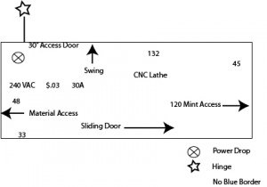
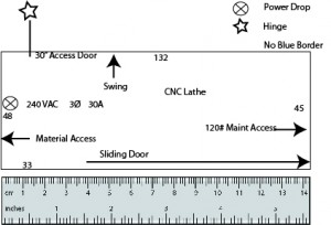
Next, I ask them to print (or draw) all of their equipment… everything with a footprint on their building floor… in the same engineering scale on paper using either using a CAD system (if they have one) or using an engineering scale and a pen. Be sure to include such information on the cutouts as:
- Equipment name.
- Gross outside dimensions (length, width & if necessary height) in the specified units (inches or centimeters). For a particularly tight location, instead of using gross outside dimensions, use a much more specific footprint shape and dimensions.
- Location of operator(s).
- Utility entry/exit location(s) along with the required capacity & flavor such as 240 VAC, 3Ø, 30 Amp… or… Air Exhaust: 30 SCFM… or… Natural Gas (10 SCFM / Hr)… or… Water: 3/4NPT, 125 psi…etc.
- Access door location and width so you include a wide enough adjacent aisle to service the equipment.
- Unusual or rare access requirements. For example, I once had a client that had several numerically-controlled lathes in their production process… all laid out it process order of course… that almost became maintenance landlocked. It seems we forgot that periodically the automatic-chip-removal conveyor had to be completely removed out from under the lathe… which required a 10 foot clearance on the right end of the lathe! Oops (almost)! We did catch it before actually implementing it on the shop floor, but only during the 3rd or 4th look at the layout? This was the, “Now that we think we have everything, what we are missing” phase!


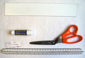
Next, we glue-stick the CAD drawings on to 2′-wide refrigerator magnet that comes on a roll (available from any signage industry supply house or Google [magnetic sheet white] or [magnetic roll white]) and cut them out with scissors or a knife and put them in their places on the sheet-metal mounted and scaled building drawing. Here is a “visual list” of the required tools.

The main problem with CAD in this environment is that no CAD operator is fast enough to keep up with the speed of layout ideas in an improvement team meeting… not even close to fast enough! I encourage you to use this refrigerator-magnet idea. (I have also tried using yellow sticky notes on paper, but the adhesive wears out after moving them four or five times, and the ones you move the most begin to fall off and move without you moving them! Also very annoying!).
Implementing the Layout
When your layout has stopped changing rapidly, after four to six iterations (Again, please see the Helix article), it will be time to commence implementation. In an ideal world, you just stop production and change everything over. However, very few situations will permit this… you DO have to keep production going! Frequently, changing the physical flow across an entire plant occurs in sequential project phases… or “flow improvement Kaizen events.” For example, changing the Diamond Drill Bit Manufacturing Company’s flow from batch-and-queue to single-piece-flow occurred in five distinct phases spread across three months.
Update: September 2020
A lot has changed both technologically & biologically (Covid-19) since this page was originally written! The main problems I had with CAD when this page was originally written are that you could not crowd enough people around the CAD operator’s screen, it took too long to get the screens to update & the printouts took too long for a rapid-layout-idea-Kaizen-Team meeting. However, fast forward to this month: I did several relayout Kaizen Meetings using my CAD & Desktop over Zoom, where everyone had their own screens & real-time updating. It worked very well! (And, Yes,… I DID apply my own advice on this page into the elements of the layout models for that client!)
